Back to Projects
CAD Carriage Design and Assembly
Engineering Design Project
Project Overview
In this engineering design project, I developed and modeled a detailed mechanical carriage assembly using Siemens NX software. The project encompassed precise design of individual components, culminating in a fully assembled carriage. The comprehensive engineering documentation and detailed drawings produced were fully compliant with professional engineering standards (BS8888), suitable for guiding accurate manufacturing and efficient assembly.
Objectives
- Create precise 3D models of a mechanical carriage, carefully designing each component individually and ensuring accurate integration into a complete assembly.
- Produce detailed engineering drawings with clearly specified dimensions, tolerances, materials, and surface finishes.
- Generate clear and professional documentation including an exploded view, isometric views, and a structured bill of materials (BOM).
- Ensure the carriage design adheres to manufacturability principles and efficient assembly practices, clearly communicated through professional visual documentation.
Methodology
The approach was systematic and adhered closely to engineering best practices:
- Detailed Component Design:
- Individually modeled components using Siemens NX, carefully defining features and dimensions.
- Components included a robust base, precise carriage structure, handles, spindle, shaft, clamps, and associated mechanical fixtures.
- Assembly Modeling:
- Assembled the individual components in NX, ensuring precise mating conditions, accurate fitment, and operational functionality.
- Technical Documentation:
- Produced detailed engineering drawings specifying precise linear tolerances (±0.2 mm), angular tolerances (±0.5°), suitable material choices (e.g., cast iron, cast aluminium), and surface finishes (clean, scratch-free).
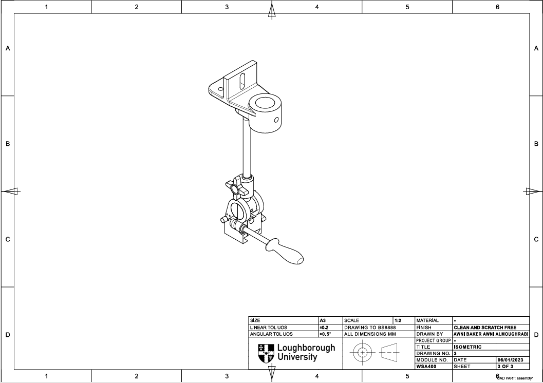
- Created an exploded view and clear isometric visuals to illustrate the detailed assembly process and internal component relationships.
- Developed an accurate and complete Bill of Materials (BOM) compliant with BS8888 standards.
Key Deliverables
- Detailed Engineering Drawings: Fully dimensioned drawings of each individual component with clearly stated tolerances, materials, and finishes.
- Exploded Assembly View: Clearly communicated the assembly order and component interrelationships to facilitate accurate production planning and assembly processes.
- Isometric Assembly Views: Provided professional visual representations, aiding clear communication with stakeholders during manufacturing stages.
- Bill of Materials (BOM): Clearly defined each component, including base, carriage, clamps, spindle, shaft, handles, and fasteners, supporting accurate production planning.
Design Innovations and Practical Considerations
- Applied rigorous engineering principles to ensure that all designed components were not only theoretically accurate but practically manufacturable, considering real-world constraints.
- Utilized Siemens NX capabilities to simulate precise fits and tolerances, preempting potential assembly challenges and improving overall design quality and reliability.
Skills Applied
Mechanical Design & 3D Modelling
Engineering Drawing and Documentation
Siemens NX Software Proficiency
Detailed Tolerance Analysis
Material Selection & Specification
Compliance with Engineering Standards (BS8888)
Assembly Design & Manufacturability
Technical Visualization and Communication